|
Click The Radio Image On The Left To Return To Homepage Feel Free To Copy Any Information On The Webpages |
| |
| Vintage Radio & Test Instrument Restoration 3 IF Transformer Repair Updated 04/11/2021
The Information Published Here Is For The Noncommercial Use Of Radio Hobbyists
All credit is given to the author Paul E.
Pinyot 2013 and
This is a pictorial example of the procedure which I have used to repair intermediate transformers in which the capacitors are suffering from silver migration.
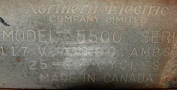
1) Start by identifying the radio. Look for a model number on the chassis or cabinet, or if that is a no-go, get the tube list, take a photo if possible, and post the tube info and radio description on an antique radios "newsgroup" or "forum". Someone is sure to help. The idea is to get the values for the I.F.capacitors, and hopefully from a schematic. If this is not possible, and if no-one is able to help with identifying the values, then you're going to have measure the inductance of each individual coil, and calculate the capacitance using formulas or capacitive and inductive reactance at the I.F. frequency.
Typical model
number:
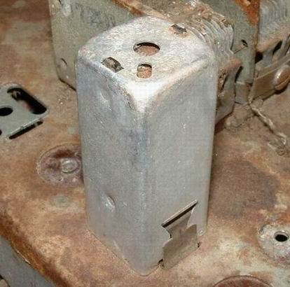
2) Identify the offending transformer (this one looks suspicious). Usually this is done either by using a modulated signal generator and your ear, or a signal generator and an oscilloscope to trace backwards from the audio stage, until you pass a stage where there is no more noise either audible or viewable on the scope.
Typical intermediate frequency
transformer:
3) Be sure that you're unsoldering the correct transformer, that it is indeed an IF transformer, and don't get them backwards when you flip the chassis over ( this leads to expressive language later!).
IF xfrmr bottom
side:
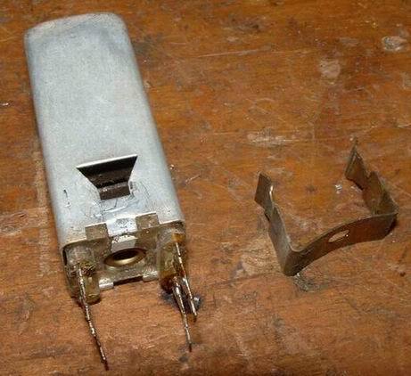
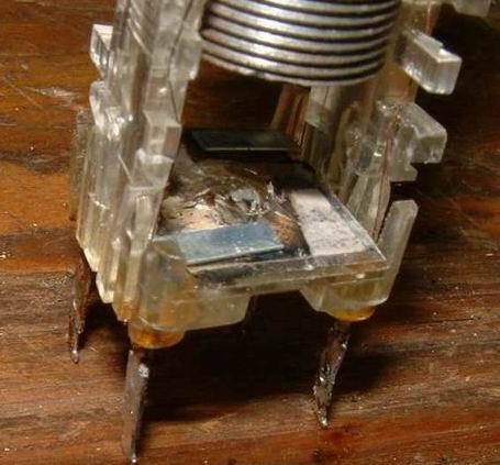
4) This next photo is what the transformer looks
like before it is pulled apart. Now for those of you who take things literally,
"pulling" is a relative term. "Gently disassemble" is probably more
accurate.
IF xfrmr out of
chassis:
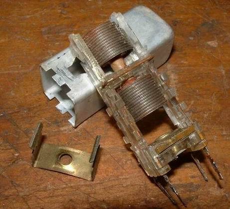
Cover taken off IF
xfrmr:
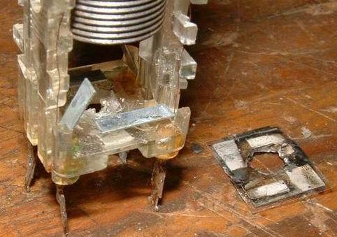
6) Here it is with the rivet drilled out, and the plastic capacitor retainer plate removed. All that is left are the two top contact strips, the mica spacer/insulator, and the two lower contact strips (not visible under the mica).
Rivet drilled out - cover plate off
capacitor:
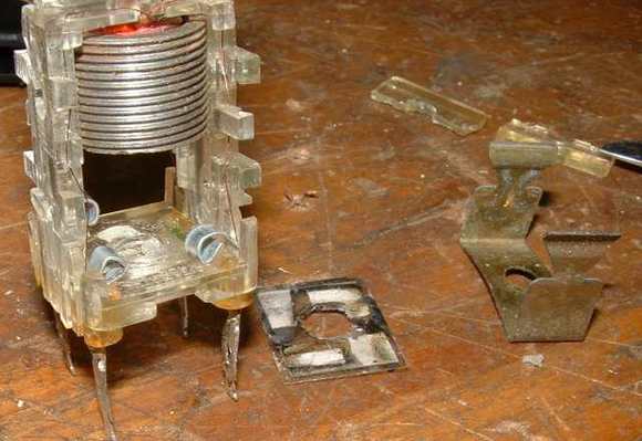
7) And once again, this time with the mica out and both contact strips showing. Lots of migration showing in this puppy! It was going to need a passport soon!! Maybe even some unemployment insurance!
Capacitor mica removed: 8) To keep the contact strips from touching, I curl them a bit. If the replacement caps WON'T fit in the can, then I glue (hot or epoxy) the strips tight into place, and solder the replacement caps onto the underside after the transformer is reinstalled into the chassis. If the replacement caps DO fit in the transformer, then..........see the next photo.
Ready for new capacitor: 9) This is "any old capacitor" which I used for the photo. It's now soldered into place and ready to go back together. In your radio, make sure that you have the correct value. You can test these transformers and capacitors out of the radio by putting an RF signal of the correct frequency (obviously) through the primary coil, and hooking your scope across the secondary using a detector probe. With this hookup, you can verify that the circuit resonates properly, and you can also peak the transformers before they go back into the radio.
New capacitor soldered into
place:
10) Here we have the transformer with new capacitors installed and the assembly slid back into the can, with the metal retaining tabs bent back into place.
IF xfrmr assembled - ready to
reinstall into chassis:
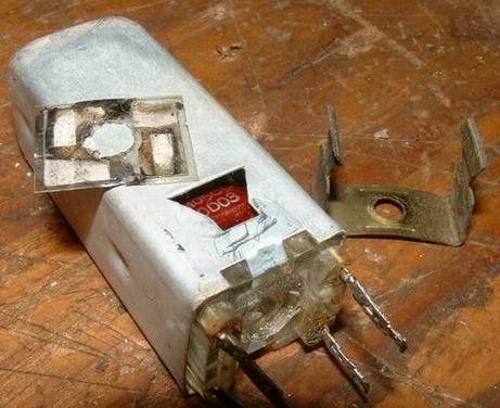
11) This shows how the clip will attach to the transformer and hold it into the chassis. It's probably a good idea to put the transformer into the chassis before installing the clip! It's easier that way!
How retainer clip fits:
Bob Krueger, AB7CQ Web Administrator 146.920/146.320 PL 123.0 444.600 / 449.600 PL 100 Repeater IRLP Node: 7515 PL 114.8 ab7cqradio@ebidpal.com |