|
Click The Radio Image On The Left To Return To Homepage Feel Free To Copy Any Information On The Webpages |
| |
|
Auto Painting Tips For The Beginner smokeyt616@ebidpal.com Author: Robert W. Krueger Tombstone, AZ 10/08/2024 Caution Before you attempt to do any automotive painting you must wear rubber gloves. You will be working with lacquer thinner, mineral spirits, acetone, various chemical agents, body fillers, etc.. Many of these chemicals can and will be easily absorbed into your blood stream through your pours, they are extremely dangerous, and they can cause cancer and other serious injury to you, including death. The same is true with wearing an approved respirator so that you don’t breathe in fumes from working with paint and other chemicals used in automotive work. I recommend a full face hooded respirator to protect your eyes. Nitrile gloves, in contrast, provide a better barrier to paints and organic solvents—the chemicals that are some of the toughest on gloves. Because they protect well and are durable, nitrile gloves (which cost about $10.00 for a box of 50 pairs) offer good value for your safety dollar. Purchase the heaviest mil thickness gloves, I believe Nitrile rubber gloves are available up to 9mil thickness and can be found at Harbor freight. This is serious business; many folks have died because they avoided these precautionary warnings. Change respirator filters on a regular basis – YOU HAVE BEEN WARNED.
Beginner’s Basic Prep Tips Before Painting The automotive painting tips presented here are an accumulation of approximately 60 years of accumulated information, when young hot rod enthusiasts were painting and customizing their hot rods, junk yard cars, and pop’s family car that their son or daughter banged up - (American Graffiti Days 50’s, 60’s & present). These painting tips are provided so you can avoid the mistakes many of us made and the skills we learned, including many skills learned from professional automotive painters, much of which will save you time, money, and heartaches. I’ll be addressing mostly the application of single stage acrylic/urethane paint and primers in these painting tips. To some extent I will touch on the application of single stage metallic acrylic/urethane paint, and application of custom painting which includes primer, basecoat, and clear coat including candy colors. Also, when you purchase a new spray gun the spray gun usually includes a small plastic filter that drops into the spray gun throat where your paint cup or disposable paint canister attaches to, DO NOT INSTALL THAT SMALL FILTER, they typically clog quickly and cause problems with paint application. Simply filter your paint, primer, hardener, and reducer through a standard paper cone paint filter. Also keep in mind as additional assurance, if you're using a disposable paint canister, the lid incorporates a built in filter, so you don't need that troublesome small plastic filter. Also, remove the filter in your disposable spray gun canister/cup if you’re spraying metal flake. I’m covering a lot of material in these automotive painting tips, it can become a bit confusing, some topics may seem redundant but they’re not, you sort of have to read between the lines.
Distance From Panel/Surface When Spray Painting
The rule of thumb is to hold your paint gun 6” – 8” from the panel/surface, this will come with practice. Too far or too close can affect the results of the finish. Preparation Before Painting (Absolute Cleanliness) 1. Initially wash the entire vehicle first with Dawn or Joy detergent and water, it’s the best for removing contaminates like wax and silicones, dry with clean towels. 2. Rubbing alcohol is safe to use on car paint. Car paint can be cleaned effectively with rubbing alcohol, which removes grease, oil, and heavy soil. Mix Ratio: 50% Alcohol 50% Water. 3. Before painting a bare metal item, wipe the surface with a solution with 1 part vinegar to 5 parts water. This cleans the surface and makes peeling less likely. The acidic qualities of the vinegar will clean and degrease the bare metal surface and help the paint adhere. 4. Sprayway glass cleaner is one of the most effective and least expensive prepaint cleaners available, it will do a fantastic job. Don’t let anyone tell you otherwise, they’re promoting expensive prepaint cleaning products, yes they’re also good, but there are other less expensive options available. Use microfiber towels for general cleaning. You can also use isopropyl alcohol as a prepaint cleaner (50% alcohol 50% water). Remember, a tack cloth is a specialty wiping rag designed to pick up loose debris or dust particles, use a tack cloth as the last step before applying paint. Clean any and all primed, filled
surfaces (like Bondo), or painted surfaces before applying clear coat. Use
microfiber, or tack cloths, spray the solution with one hand and wipe with the
other hand. If you’re spraying single stage paint: for the first coat lay down a
light tack coat on the entire vehicle, it’s recommended that you lay down at
least two remaining full coats. If you wish for more added durability, you can
lay down a clear coat. Special Note: If you’re going to be spraying plastic surfaces or fiberglass surfaces, you should, after basic cleaning preparation, spray these surfaces with “ADHESION PROMOTER.” Adhesion promoter is a substance or chemical compound that is used to enhance the bonding between two surfaces. It works by providing a reactive surface for the adhesive material to attach to, namely the paint. You should always clean any surface you plan to paint, including metal. Any oil or dust left on the surface will prevent the paint from sticking. You can also use acetone, or Klean Strip Prep-All to wipe down the surface before you paint. Automotive commercial cleaners are expensive; the household cleaners discussed above are just as effective. If you don’t have any of these cleaners available, you can use Windex. DON’T TOUCH ANY SURFACE TO BE PAINTED WITH YOUR HANDS OR FINGERS, use rubber gloves, the oils from your body will prevent the paint from bonding properly. Lastly, as a last step, use a tack rag to wipe down surfaces to be painted.
Where Do I Start Painting?
Good question. Automotive painters will all have their own preferred method of where to start and finish the application of paint, generally you start from the top and work your way down. The following is the general rule of application steps:
1. Roof 2. Hood & Bumper 3. Trunk & Bumper 4. Fenders 5. Doors 6. Quarter Panels
This isn’t a hard and fast rule, just a general rule, I’ve known some painters that brake all the rules and move all around the vehicle randomly ...... NOT ADVISABLE. You don't want overspray falling on your already painted surface.
SCOTCH BRITE GRIT CHART (Scuffing) 3M Scotch Brite Nylon Pads: 7445 - White pad, called Light Duty Cleansing - (1000) 1200-1500 grit 7448 - Light Grey, called Ultra Fine Hand - (600-800) 800 grit. 6448 - Green (?), called Light Duty Hand Pad - (600) 600 grit 7447 - Maroon pad, called General Purpose Hand - (320-400) 320 grit 6444 - Brown pad, called Extra Duty Hand - (280-320) 240 grit 7446 - Dark Grey pad, called Blending Pad (180-220) 150 grit 7440 - Tan pad, called Heavy Duty Hand Pad - (120-150) 60(?) Blue Scotch-Brite is considered to be about 1000 grit. Foam Polishing Pads Color Information Orange (Coarse) - Foam Polish Pad Standard Grade Cutting Pad, Excellent For Enamels, Acrylics And Urethane.
Orange: Medium-heavy pad (firm & high density), ideal for scratch and defect removal. This pad offers the correction of a typical compounding pad while at the same time allowing the polishing ability of a light cut foam pad. White: Polishing pad, used to follow up after using the orange cutting pad. It’s soft enough to be gentle on paintwork, but firm enough to remove marring, light swirls and holograms that dull your vehicle's finish. Yellow: polishing pad (aggressive pad), designed to apply compounds or polishes to remove serve oxidation, swirls and scratches. Only be used on oxidized and older finishes. Black: Finishing pad (super fine), has no cut so it can apply thin, even coats of waxes, sealants and glazes. Can withstand added pressure during final finishing to deliver a perfect result. Blue: Light polishing pad, delivers a super fine finish for use with ultra fine polishes, glazes and light surface cleaners. Sandpaper Grits You’ll need a selection of 25, 35, 60, 80, 100, 200, 400, 600, 800, 1000, 1500, 2000, 3000, & 5000 grit dry sandpaper and 100, 200, 400, 600, 800, 1000, 1500, 2000, 3000, & 5000 wet sandpaper.
Acrylic Enamel & Urethane Paint Compatibility
You can spray single stage acrylic enamel over single stage urethane paint, or vise versa. It’s always best to scuff the surface to be painted and wet sand it with 400 - 600 grit, you can also prime it with a surfacer/sealer to insure a perfect bond. Urethane adds durability to the finish. Can You Spray Single Stage Paint Over Existing Single Stage Paint? The answer is YES. It’s recommended that you sand with 320 grit, working your way up to 600 grit, then re-clean the surface prior to applying your color, remember to tack rag the surface to be painted. Spraying Clear Coat Over Single Stage Paint Can you spray clearcoat over single stage paint, the answer is YES. Actually spraying urethane clear coat over single stage paint whether urethane or enamel single stage will make the paint even more durable. However, the caveat is that you have an approximate 18 hour window to accomplish this after spraying the single stage paint, or base coat. Single Stage Acrylic Enamel/Urethane Paint Systems Acrylic Enamel is a Professional Easy-To-Use Single-Stage High Gloss Paint Coating System that is Designed for Overall Automotive Refinishing but is also used as a Fleet and Industrial Equipment Coating. AE is an easy to spray fast-drying topcoat system that provides a long-lasting and very high gloss finish result. AE is a very durable, chemical and solvent resistant coating that also resists chipping, cracking, and UV ray fading. Acrylic enamel has an 8 to 1 mixing ratio, 8 parts AE Paint Color to 1 part AE3001 Wet Look Acrylic Hardener. 2 parts of optional additional reducer may be added for a Ratio 8:2:1, 8 parts paint, 2 parts reducer, 1 part hardener. Acrylic Urethane is a High-Performance Professional Easy-To-Use Single-Stage High Gloss Paint Coating System that is Designed for Overall Automotive Refinishing but is also used as a Fleet and Industrial Equipment Coating. AU is an easy to spray fast-drying topcoat system that provides a long-lasting and very high gloss finish result. AU is a very durable, chemical and solvent resistant coating that also resists chipping, cracking, and UV ray fading. Acrylic urethane has a 4 to 1 mixing ratio, 4 parts AU Paint Color to 1 part AU4001 Wet Look Urethane Hardener. 2 parts of optional additional reducer may be added for a Ratio 4:2:1. 2 parts of optional additional reducer may be added for a Ratio 4:2:1, 4 parts paint, 2 parts reducer, 1 part hardener. Base, Clear Coat Or Primer Single-Stage High Gloss Paint Coating Systems are Designed for Overall Automotive Refinishing. It’s an easy to spray fast-drying topcoat system that provides a long-lasting and very high gloss finish result. It’s a very durable, chemical and solvent resistant coating that also resists chipping, cracking, and UV ray fading. Single Stage Paint Has a 8 to 1 mixing ratio, 8 parts Paint Color to 1 part Wet Look Acrylic Hardener, or 4 to 1 mixing ratio, 4 parts Paint Color to 1 part Wet Look Acrylic Hardener. Single stage paint is a 2.8 VOC when used as packaged, as no reducer is required (optional reducer sold separately). The optional additional reducer may be added at a rate of up to 1 quart per gallon (25%) if desired. Use XR Series Exempt Reducers to maintain a 2.8 VOC Level or use the UR Series Urethane Reducers for a 3.5 VOC Level. Optional Reducers Are Available Separately. My personal recommendation is that you should always use/add reducer to the paint. Let me explain. Depending on the climate temperature and humidity in which you will be spraying the paint, it will have an impact on how the paint will flow out and prevent adverse reactions like orange peel. There are three reducers available for climate: Fast: 60 – 70 degrees Medium: 70 – 85 degrees Slow: 85 degrees and above Many professionals prefer slow reducer above 80 degrees. Paint Hardener/Activator Temperature Range Fast 55 – 65 degrees Primers are typically 3:1 or 4:1 ratios, single stage paint is generally an 8:1 ratio, which means they consist of only the paint or primer, hardener is an additive, but NO REDUCER. Caution: I always add reducer based on the temperature in which you will be spraying/applying the primer, single stage paint, or clear coat. In temperatures up to 70 -85 degrees use a mid temp reducer, in temperatures 85 and above use a slow reducer. It’s wise to do this because the paint will flow better, will help prevent orange peel, and help prevent other adverse reactions. So I recommend mixing ratios of 3:1:1 or 4:1:1 depending on the primer product you’re using, and if using a single stage paint with a 8:1 ratio change that to 8:1:1 and add reducer. All Acrylic Enamel/Urethane paints and primers require hardener.
Example: The first part is paint, the second part is hardener, and the third part is reducer. Example: Based on a total volume of 8oz of mixed product you need for the job, and the manufacturers specified paint ratio of 8:1:1, this would = 5.33 oz paint, 1.33 oz of hardener, 1.33 oz of reducer.
Paint = Single Stage Paint – Base Paint Color – Clear-Coat.
Additives = Reducer & Hardener. Always remember that when mixing paint, first add the paint, then the hardener, then the reducer, unless the paint manufacturer specifies otherwise.
Different Kinds of Automotive Primers The kind of car paint primer you end up using will vary with your project needs. You can ensure a lasting, high-quality auto paint job and extra rust protection with a good primer base. Different types of automotive primer will also withstand sanding differently, and depending on your project, you may want to consider this. You will need to apply three to five coats of primer, I would suggest 4 to 5 coats to deal with any imperfections and insuring that when you block sand the body/panels that they will be perfectly straight, and so you don’t break through the primer, once again preparation is 100% of body work to insure as close to a perfect paint job as possible.
Explanation Of Mixing Ratios You have total parts that together which equal total ounces. Divide total ounces by total parts to find out how big each 1 part is.
Example: 20 Total Ounces & 11 Total Parts
Each part is 1.81819 oz (rounded off) so 8 x 1.81819 = 14.54552 oz. 1 x 1.81819 = 1.81819 oz. 2 x 1.81819 = 3.63638 oz.
Always remember that when mixing paint, first add the paint, then the hardener, then the reducer, unless the paint manufacturer specifies otherwise. Restoration Shop Acrylic Enamel Some Mix Ratios Prep: Primer & Sealer – Mix Ratio: 3:1:1 (Primer, Hardener, Reducer), Primer Pot Life: 2 - Hours Mixing Ratio Paint: 8:1 (Color, Hardener, No Reducer) 1 Part AE3001 Wetlook Mid Hardener (Slow, Mid, Fast)
2 Parts Urethane Reducer (Slow, Mid, Fast) Pot Life: 8 Hours
Drying Time Between Coats: 10 – 15 Minutes @ 70 Degrees Required Coats: 2 – 3 Coats Dust Free: 40 50 Minutes
Tack Free: 3 Hours
Spraying Rustoleum Oil Based Enamel What Reducer/Hardener To Use Reducer Is Basically A Paint Thinner
Mix Ratio: 4:3:1 (Average) The best way to thin Rustoleum oil-based paint for spraying is to mix 6.5 ounces of acetone for every gallon of paint.
Mineral Spirits = Slower Dry Time 80 Degrees & Above.
Acetone = Faster Dry Time Below 80 Degrees.
Hardener/Catalyst: Any Hardener Will Work (Slow, Mid, Fast). Substitute Paint Reducers & Hardeners In a word, “NO”, don’t use substitutes for paint reducers and hardeners. Paint is based on chemistry, not all paints are created equal. DO NOT SUBSTITUTE ACETONE OR PAINT THINNER for automotive paint reducers and hardeners. YES, lot’s of individuals say you can do this, but most of this is ill advised, it’s best to error on the side of caution. YES, automotive paint reducers and hardeners do contain some acetone, but the entire physical chemistry of automotive paint is made up of other components/chemicals to off to offset the harsh effects of using acetone only as a paint reducer. Using straight acetone as an automotive paint reducer is not advisable, it can in some cases cause damage to the paint and cause it to lift, or result in other harsh affects damaging your paint job, either now or later. Use recommended paint reducers and hardeners, YES, they are more expensive, but you won’t risk damaging your paint job. The same applies to using straight paint thinner. Note: If spraying Rustoleum oil based Enamel, you may use acetone, or paint thinner as prescribed by the manufacturer’s directions. Remember, the chemistry of automotive acrylic enamel/urethane paint and Rustoleum oil based enamels are different in their chemistry, use what the paint manufacturer recommends. Guide Coat & Paint Blender Guide Coat is used in the dry primer sanding process to identify surface imperfections such as pinholes and deep scratches in primer. When sanding polyester filler, it ensures the filler is flat with no ripples and that the body styling lines and contours are straight and correct. You can simply use a black or gray primer as guide coat, just dust the panel and it will reveal the low spots and imperfections, you can then block sand until the guide coat disappears and your panel will be flat. Paint blender allows you to taper the paint out into the adjacent panel in a way that gradually loses the difference to your eye. A well done blend will make it impossible for you to see the repair work. It is important to note that, on blend panels, if there are chips or dents, they will still be there. Blender is available in both color or clear coat.
Bare Metal Surface Preparation (Vehicle Stripped)
If you have removed all the paint from a vehicle, down to bare metal and done all the necessary body work, a basic method is to spray the entire vehicle with an acid etching primer and then spray a polyester filler (a special primer). At this stage your next step is to spray the surface with a guide coat, then block sand, finally fill any imperfections, then spray on 3 – 4 coats of filler primer with hardener. Lastly, spray the entire vehicle with guide coat again and block sand the entire vehicle so the surface is “FLAT”.
The best method, assuming you want to do a highly professional surface preparation for high end finishing (custom show car) the following surface preparation is recommended.
Remember, always wear gloves, always wipe the painted surface with a cleaner using a microfiber cloth and tack rag through each of the steps mentioned above before sprayer each coat, whether primer or paint.
This type of surface preparation is generally done when the entire vehicle has been completely stripped down to bare metal; all body work has been completed as previously discussed to insure that all the panels are completely flat and straight to achieve a show car result.
Spray Painting
All the comments in this spray painting tips document are intended as a general overview of the ”how to process”, they are not intended to be an absolute for every spray painting application, what does that mean? They are intended as a starting point for adjusting your spray gun. There’ no one out of the box perfect spray gun adjustment or setting for all spray guns, there are numerous factors involved in setting up of a spray gun. All spray guns perform differently, the type of paint, primer, clear coat, reducer, hardener, ambient temperature, pressure setting, fluid setting, fan adjustment, and other factors affect the end result of the finish you achieve. You the sprayer must become familiar with the spray gun you’re using and learn what works best for that particular spray gun. Spray gun designs vary considerably, some also have digital readouts for pressure, some are low volume low pressure (LVLP), and some are high volume high pressure (HVHP) designs.
Here are a few suggestions for setup of your spray gun, you will still have to find what works best for the spray gun your using, but this is a starting point. One of the spray guns I use is an AEROPRO A610 LVLP spray gun.
Primer Application: Starting Point at 26 PSI Single Stage Paint: Starting Point at 26 PSI Base Coat Paint: Starting Point 26 PSI Intercoat Base/Flake: Starting Point 28 PSI Clear Coat: Starting Point 30 PSI
Adjust accordingly up or down.
You will have to practice with the spray gun you own to arrive at what works best for the particular spray gun. You can setup a piece of blank paper or cardboard and make adjustments, checking for proper fan size, fluid delivery, air pressure, and atomization. Basically you’ll be adjusting for distance from the panel/surface your spraying, the fan size, proper atomization of the paint droplets, and speed of walking the delivery of the paint to the panel surface so you don’t wind up with too wet or dry delivery of the paint (atomization of paint droplets), orange peel, or paint runs. Another good idea, if possible, is get an old fender, door, or other panel from a junk yard, or from someone that has one laying around in their scrap pile, you can use it as it as a practice panel for paint application. Also, when you purchase a new spray gun the spray gun usually includes a small plastic filter that drops into the spray gun throat where your paint cup or disposable paint canister attaches to, DO NOT INSTALL THAT SMALL FILTER, they typically clog quickly and cause problems with paint application. Simply filter your paint, primner, hardener through a standard paper cone paint filter. Also keep in mind as additional assurnace, if you're using a disposable paint canister, the lid incorporates a built in filter, so you don't need that troublesome small plastic filter. Once again, also remove the filter in your disposable spray gun canister/cup if you’re spraying metal flake. Just be patient, it’s a learning process like anything else. There’s a wealth of information available on YouTube you can access to help with the learning process.
HVLP Spray Guns (General)
Use 28-29 PSI for clear coat and 26-27 PSI for base coat, use 25 PSI for primer. NOTE: If in a very humid climate it’s advisable to keep the compressor drain slightly open to keep water from entering the line. Be absolutely sure to install a quality filter drier unit at the output of the compressor output and a filter at the inlet of the spray gun. LVLP Spray Guns (General) LVLP Low Volume Low Pressure Spray Gun Settings for (LVLP) spray guns will average 20 - 26 PSI for primers, base, and clear coat.You can spray a vehicle using a 21 – 25 gallon compressor. Hold spray gun 6 – 8 inches from surface with steady motion from side to side (distance is also determined on type of primer, base coat, clear coat, and whether applying a tack coat, medium coat, wet coat, or mist coat). Spray gun technology and paint improvement has come a long way, today there’s a tendency to use single stage acrylic/urethane paint and LVLP (low volume low pressure) spray guns that can also be used with small compressors so the DIY’ER can paint their vehicles to save money in this inflated economy, even an inexpensive (cheap) paint job can cost you $400 - $500. In this document I refer to spray gun pressures for both HVLP and LVLP spray guns, with pressures ranging between 26 – 30 PSI, in fact we find that new spray gun technology has made it possible to spray at pressures as low 14 – 22 PSI whether spraying primer, base, clear coat, or single stage paint producing beautiful finishes. You’ll have to spend some time learning what your particular spray gun is capable of doing. NOTE: If in a humid climate it’s advisable to keep the compressor drain just cracked open to keep water from entering the air line. Be absolutely sure to install a quality filter drier unit at the output of the compressor output and a filter at the inlet of the spray gun.
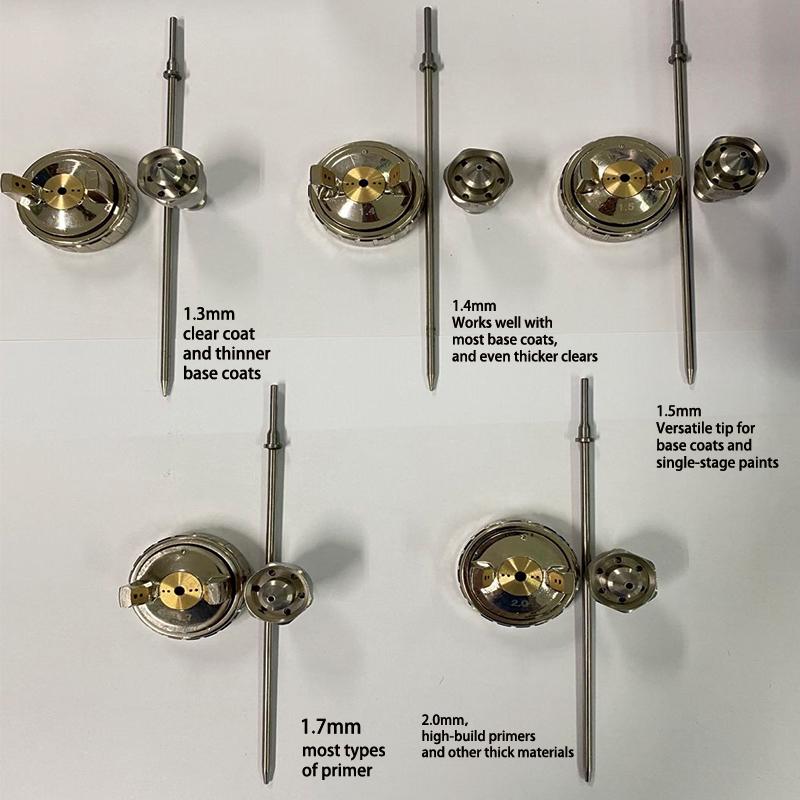
Spray Gun Recommended Nozzle Selection
Paint Overlap & Wet Edge When spraying a basecoat or clearcoat it’s best to never go below a 50% overlap, I recommend a 70% overlap to keep a wet edge and prevent dry spots or striping. Obviously there are circumstances that require changes in paint application such as touchup, but as normal practice when doing a paint job 50% - 70% overlap is pretty much the rule of thumb. Recommended Average Spray Gun Nozzle Size: 1.4 All Around Tip – clears, base coat, single stage paints. 1.8 For Primer - will apply primer quickly. Approximate Amount of Paint Required For Painting When painting an averaged sized car, a one gallon kit (of enamel/Urethane paint) is usually just enough for a medium sized sedan car or light truck. We always suggest to mix up a small batch of paint or clear coat and spray a test panel before you go at your project. Make sure you dial in your settings, mixture, and technique so you can quickly and efficiently lay your paint or clearcoat. If you have a nice selection of activators you can paint throughout the warm months of the year.
Paint Required – 1 Mist Coat 1 Wet Coat (Paint Only) Fender = 8 Sq. Ft. – Paint = 5.12 oz Hood = 20 Sq. Ft. – Paint = 12.8 oz Roof = 18 Sq. Ft. – Paint = 11.52 oz Door = 8 Sq. Ft. – Paint = 5.12 oz Quarter Panel = 14 Sq. Ft. – Paint = 8.96 oz Tail Gate = 11 Sq. Ft. – Paint = 7.04 oz Add Reducer 25% & Hardener 25% Quart = 100 – 120 sq.ft. Sq. Ft. = .27 oz - .32 oz Painting Single Stage Enamel And Urethane Paint 1. Priming & Seal Surface 2. Shoot A Tack Coat 3. Shoot One Medium 4. Shoot One Wet Coat 5. Shoot One Mist Coat (Drop Coat) Note: If you’re going to be spraying plastic surfaces or fiberglass surfaces, you should, after basic cleaning preparation, spray these surfaces with “ADHESION PROMOTER”, then follow with primer/sealer. Do not confuse primer with adhesion promoter, they are two different things and serve different purposes in automotive painting. Typically, for an entire car or small truck (1/2 – ¾ ton) you should plan on 5 quarts of paint if shooting single stage urethane paint. If you’re shooting base coat and clearcoat, plan on 5 quarts of paint and 5 quarts of clearcoat. Be sure to purchase the required reducers, and hardeners. It’s always better to have extra then not enough to complete the project. Also, any left over paint, clear coat, reducers, and hardeners will come in handy for any needed touch up or repairs. Small Cars – Miata, Minis, Model A roadsters and the like typically take about two quarts of single stage paint to apply enough coats to cover them, plus the reducers and hardeners. Medium to Full-Size Cars – Your typical muscle car, modern sedan, or full-size car usually will use most of a gallon of single-stage paint. Usually it is best to buy a gallon kit. If you’re spraying base coat/clear coat, it may only take 2-3 quarts of base coat to cover completely, however, professionals will usually recommend a minimum of one gallon to 5 quarts of single stage, base coat, and clearcoat.
Trucks and Vans – Obviously, these are bigger and you will need more paint. Buy at least a gallon plus an extra quart of paint for regular sized trucks and two extra quarts for vans, full-sized SUVs and crew cab trucks. Don’t forget, you have to paint inside the bed too. If spraying base coat/clear coat, a gallon of color may be enough but buy more than a gallon of clear. Clear Coat – Always buy a full gallon kit of clear and mix as needed. You can always use leftover paint that has not been mixed with activator for spot repairs or small projects. Same Color Respray – If you are respraying a typical car the same color because the clear coat has failed or after collision repair, you will likely only need about two quarts of base coat color. You will still need a gallon of clear, though. I would always recommend a gallon of color paint and gallon of clearcoat, better safe than sorry; you don’t want to run out of paint. Remember, you will also need reducer and hardener. Single-Stage vs. Base Coat/Clear Coat – You will use more single-stage paint then you will basecoat to cover any given car. But chances are you will use less total paint when you compare the amount of basecoat and clear coat applied compared to the single-stage paint. Temperature Range Of Hardeners & Reducers – (Activators & Hardeners Are The same Thing) 1. Slow Reducer/Activator– Slow activator is great for when you may be painting on a hot summer day when the temps are over 80F. Once you fine tune your mixture you can use this on a hot day and your paint will flow out nice and flat and you’ll have enough time to lay all that you’ve mixed in your gun. Using this activator on too cool of a day would cause the paint to take much longer to flash and can cause imperfections in the paint. If you are in a pinch you could tweak the mix ratio, but do this with care! 2. Medium Reducer/Activator– We formulated this activator to be the best “all-around’ activator when painting. If you are unsure which activator to choose, this one will work in most climates. Just remember that when you reach higher temps around 80F it may flash too quickly (causing “dry” spots) and with the temps under 70F it may take quite a while longer than normal to flash. 3. Fast Reducer/Activator– Spraying on a cool fall afternoon or on a night when the temps are under 70F? Then you need our fast activator! It will speed up the flash time and allow you lay your additional coats of paint or clear coat in a reasonable amount of time in cooler weather. In a pinch you can use our Medium activator as well, but remember it could raise your flash/cure times greatly! Note: In hot climates like Arizona where I reside temperatures reaching 90 degrees and above can cause the paint to dry too quickly, leading to poor adhesion and lead to a compromised finish. High temperatures can also cause the paint to wrinkle or sag. 3M Bondo, RAGE Body Filler, & Date Coding EU1118M1040017
First digit 1= year. It would mean it is made in year 2021. Next three digits 118= days in the year. Made on 118th day. Your product was made on the 118th day of 2021. The Bondo(R) Fillers have a 16 month shelf life from that date. One of the best fiberglass body fillers is RAGE, Bondo is a fall back filler, Rage Ultra is the world’s best sanding body filler. They have a variety of body filler products, they’re not the cheapest, but not really that much more than Bondo, by the gallon you’re looking at around $100. You can also mix their body fillers to achieve the performance you’re looking for. Surface Sealer Vs Epoxy Primer Vs Etching Primer A primer surfacer/sealer is used to correct minor surface irregularities and to stop your top coats from being absorbed by a more porous substrate. YES, you can spray 2K primer surfacer/sealer over existing acrylic/urethane paint. It also helps to remove/hide imperfections. It’s also used to cover imperfections and create a smooth surface for the topcoat to adhere to and prevent rust.
Epoxy Primers when used on metal are for corrosion protection and helping with adhesion. It’s a NON-SANDING Primer! The Correct Name Should be "EPOXY SEALER", because that's all it is! This product is a sealer to use on different surfaces for protection from foreign elements to eliminate contamination! But it's not the only primer that you can use for bare metal, it's just one option. Etch primers are convenient for the priming of all types of metal that require a very quick turn-around time. They only require a very thin coat in order to etch the metal surface and create a tenacious bond. Zinc phosphate pigment offers some degree of corrosion protection. The fast dry characteristics allow the topcoat to be applied shortly after primer application. Self-etching primer is really nice to work with. It dries fast, and tough. Primers take between one and four hours to dry on average. However, the exact drying time depends on the primer type, room temperature, humidity, and the surface you're painting. Most manufacturers advise waiting at least 60 minutes before painting over primer. Both Epoxy Primer and Self-Etch primer (Self-Etching primer) can be used on bare metal. Both provide corrosion protection, and both can be top-coated with primer surfacer. If you’re doing some body work and you have some bare metal, you don't want to just put regular primer surfacer because it does not have the corrosion properties like Epoxy or Self-Etch. So, how do you choose if you use Self-Etch or Epoxy? It’s really just a preference and depends on your individual variables. With a restoration shop, they're probably using more epoxy. If they're a high production shop, like a body shop that runs a lot of cars through, they're probably using Self-Etch. The reasoning behind that, Epoxy is the only primer that you can put body filler on top of. You shouldn't apply body filler on top of a Self-Etch primer or primer surfacer, but with epoxy you can. Our opinion is if you're going to be doing some body work, the best thing is to put Epoxy Primer on top. That way, you seal it all off and prevent it from any rusting, and then you can do your body work. You can spray self etching primer over body filler, you can apply self etch primer over fully cured filler. As long as you let the primer fully cure and then scuff the surface it will be fine. As a matter of FACT body filler works better when applied over a protective primer (epoxy or self etching) simply because the primer helps protect the bare steel from moisture. Body filler is extremely porous and will absorb moisture just from the air. That moisture can then attack the underlying steel if its not protected with a good quality primer. It would be better to use an epoxy primer but self etching will work fine. It's just yesterday's technology. Remember: You must spray a coat of surfacer/primer/sealer over self-etching primer before spraying a base coat or single stage acrylic/urethane coat over it.
Personal Note: Based On my experience, before spraying any Acrylic/Urethane base coat or single stage paint over primer its better that you let any applied primer to cure for at least 48 hours. If you fail to do this you could or may experience an adverse reaction to the applied primer, base coat, or single stage paint.
Some advantages of Epoxy over Self-Etch: Epoxy is very friendly (user friendly) and is very compatible with other products. You don't have to worry about anything lifting like you might with a Self-Etch primer. With epoxy, you can lay it over just about anything; body work, sanded paint, metal and you're going to be fine. With Self-Etch, if put it over different layers of paint, if put on too wet, it's going to lift because Self-Etching primer has acid in it. Be aware of this. Epoxy can be more expensive, but then again….when you are already spending hard earned money on restoring the car of your dreams, a few extra bucks isn't going to break the bank. Some advantages of Self-Etching over an Epoxy It's a little bit straighter forward. There are no induction times with Self-Etching primer. There are 1K products that work well for corrosion protection, that are also available in spray cans. So, if you have just a small area and you're wanting to apply such corrosion protection to, a Self-Etching primer in a spray can may be the way to go. Very simple. There are a lot of ways to do this. If you have a bigger area, let's say bigger than a gold dollar coin, you can mix up some epoxy and use that. If it's smaller than that, you could use a spray can of Self-Etch primer. The advantages Self Etch over other metal primers are as follows:
1. Provides excellent adhesion over a variety of different metals.
2. Can be applied with minimal preparation (clean, degrease and abrade, refer to data sheets).
3. Rapid cure, allowing over coating with thin film topcoats in substantially less than 1 hour.
4. Zinc phosphate pigmentation offers some degree of inhibitive corrosion protection. Lastly, there is one third option, and that's a DTM, Direct-to-Metal primer. This is a primer surfacer, so you get your sandability with it. But it also has some acid in it, which acts like a Self-Etching primer. DTM can be applied directly to steel and then sanded just like a primer surface.
Important Notes: On epoxies, some have an induction time. Think of it as they have to kind of get to know each other a little bit before they bond. Compressors Tricks & Tips Many DIY spray painters do not have a $1,000 - $2,000 air compressor setup to deliver sufficient air volume to the spray gun (i.e. HVLP Spray Guns & air tools), however, some may have a two smaller compressors like 26 - 30 gallon size compressors equipped with 2Hp - 2.5Hp compressors like those found at Harbor Freight and Walmart, example: Campbell Hausfield 26 - 30 gallon compressors. Although it’s possible to spray a vehicle with a small air compressor, in general bigger is better. The issue here is that it’s best to have an air compressor that’s capable of delivering sufficient air volume for the spray gun (i.e. HVLP spray Guns & air tools). If by chance you have two smaller air compressors you can join them together by constructing a simple air manifold and joining the output from both compressors to provide sufficient air volume to feed your spray guns, air/moisture filtering, and air tools. Quite often you can find compressors on the “CHEAP”, at yard sales, or in the want ad’s. Thinning Latex Paint For HVLP Or Wagner Paint Sprayer In general, thinning latex paint should be done at a minimum of 10% or 1 gallon of paint to quarter cup water. If you are using an HVLP sprayer or handheld system, you might have to increase your water percentage to 20-30%.
What is Floetrol, it’s a latex paint additive used as a conditioner and thinning latex paint. If you don’t have any water to use, Elmer’s Glue is probably your best option for a Floetrol substitute. You will get the same pouring consistency as Floetrol if you dilute your glue with water. Elmer’s Glue-all (similar to Floetrol) will dry your painting to a matte finish. Spray Gun Settings For HVLP & LVLP Spray Guns Ok, there are three settings that are required to properly adjust your spray gun, these are working & static air pressure, fluid, and fan adjustments. These settings are also dependant on the spray gun setup you’re using (obviously). It’s best to show how this is accomplished in a video. I’m including two excellent videos on this subject.
1. https://www.youtube.com/watch?v=pNfjSFyGYiM 2. https://www.youtube.com/watch?v=joOv4oLKj4U" Please keep in mind that there are numerous variables for setting up the spray gun, these include, climate (i.e. temperature), spray gun quality, working & static air pressure, fluid, and fan adjustment. The above video will give a pretty good handle on how to make these adjustments; obviously, you’ll develop a feel for the particular spray gun you’re using. Lastly, be absolutely sure to select the correct paint activator (hardener) and paint reducer for the temperature climate you will be painting in, failure to select the right activators and reducers will result in a failed paint job.
Like anything else, it’s a skill that you learn, this little tutorial should help you get started in the right direction. “REMEMBER, IT’S ONLY PAINT”. Primer & Paint Mix Ratio
You can spray the primers noted below without reducer, however, it’s generally advisable to add reducer to the mix so the paint will flow out better and prevent orange peel, especially when temperatures are above 80 degrees. Remember that primer is “paint”, not an additive, reducers and hardeners are additives. Single stage paint, base coat, & clear-coat are all “paint”, the first part in the mix ratio, the second part is reducer, the third part is hardener. Fast – Medium – Slow Reducers & Hardeners There are three reducers available for climate variations: Fast: 60 – 70 degrees Medium: 70 – 85 degrees Slow: 85 degrees and above
Professionals prefer slow reducer and hardener above 80 degrees, especially in higher humidity. Some trial and error may be necessary to find what works best in your climate with the products you are spraying. Here are mix ratios for 1 pint of sprayable primer or paint:
1 Pint SpeedKote Primer 4:1:1 Primer: 5.33oz – Slow Reducer: 1.33oz – Hardener: 1.33oz 1 Pint KustomShop Primer 3.1.1 Primer: 4.8oz – Slow Reducer: 1.6oz – Hardener: 1.6oz
1 Pint TCP Single Stage Paint 8:1:1 – Paint: 6.4oz – reducer .8oz – Hardener .8oz Explanation Of Mixing Ratios I’m repeating the explanation/examples of how to determine mixing ratios for paint, reducer, and hardener so you have a better understanding of how this is accomplished. In one of the examples on the previous page you have total ounces of product that equal 8oz (1 pint) made up of paint, reducer, and hardener with a mixing ratio of 4:1:1. Divide the total ounces (8oz Pint) by the total parts (ratio) which will give you the ounce(s) per part. Explanation: A ratio of 4:1:1 means that you have 4 parts paint, 1 part reducer and 1 part hardener for a total of 6 parts. Divide 8oz (1Pint) by 6 total parts, each part then equals 1.333 oz, then multiply 4 x 1.333 which equals 5.333 oz of paint, then mutiply 1 x 1.333 which equals 1.333 oz of reducer, then multiply 1 X 1.333 which equals 1.333 oz of hardener. 5.333 oz + 1.333 oz + 1.333 oz = 7.999 oz. If you add this all together it equals 8oz (1 pint). Another example: Let’s say you have a 32oz paint cup and you want to mix 32oz of product to spray on a vehicle and the ratio is 8:1:1. Add up the total parts, 8 + 1 +1, that totals 10 parts. Divide 32oz by 10 parts, that equals 3.2oz per part. Now multiply 8 x 3.2 that equals 25.6oz of paint, add 1 part of reducer which is 3.2oz and 1 part of hardener which is 3.2oz, you now have a total of 32oz of product to spray 25.6 + 3.2 + 3.2 = 32oz. Always remember that when mixing paint, first add the paint, then the hardener, then the reducer, unless the paint manufacturer specifies otherwise. Custom Color Blending Where It’s Used DELTRON® NXT™ DBC500 Color Blender is intended for use as a tool to blend and intermix basecoat colors, tri-coat pearls, and metallics. DBC500 may also be used as a fast-drying, cut-in clear for NXT & DBC color in areas that are not exposed to direct sunlight.
Example Candy Paint Projects (3 Stages & Above)
Basically you spray a primer sealer, then your silver metallic, then metal flake mixed with reducer and DBC500, lastly you would spray three coats of clear coat.
Remove the filter in the spray gun cup/canister if spraying metal flake.
Most of what has been touched on here has been using single stage acrylic and urethane paints, however, if you’re into spraying custom candy colors including metal flake make note of the following:
Fancy custom paint (colors) actually can consist of more than 3 stages, they can include application of a primer coat, a pearlescent top coat, a color base coat, and finally clear coat, actually we could call this a 4 stage paint project, and if adding metal flake we could call if a 5 stage paint project.
My Favorite Colors
Brandy Wine, Cobalt Blue, Candy Apple Red, & Candy Burnt Orange. These are beautiful custom show car colors, expensive to apply and require highly skilled painters with years of experience. The material cost alone can range into several thousands of dollars. The final cut, rub, and polishing can be extremely labor intensive. Can You Paint Your Car In A Garage (Painting History) YES & NO. 60 – 65 years ago custom car, hot rod enthusiasts, and some of us teenagers who dented up pops family vehicle were building and painting these vehicles in the back yard and painting them in sheds and garages, however, there are some special skills that must be observed when doing so. The old DIY shed or garage has to be prepped before painting, but keep in mind that such a homebrew paint booth “is not an OSHA approved paint booth.” 1. You will need to install some sort of minimal ventilation and filtering. If the shed or garage has windows or openings on each wall, one window/opening can be used for fresh filtered air; you will need to fabricate some sort of a filter that will filter the incoming and exhaust air. 2. You will need to exhaust harmful contaminates solvent orders from spraying paint and filter them before they’re exhausted to the outside environment. In today’s world your neighbors won’t appreciate the smell and complain, there’s a good chance they will call the cops if you don’t take steps to filter these contaminates and solvent orders, and YES, they can be harmful to everyone if you don’t. 60 years ago no one gave a hoot, that’s probably why so many of us wound up with cancer and other respiratory diseases, plus most of us smoked back then, boy I loved cigarettes (Luckys & Pall Mall) I quit when I was 35 but enjoyed everyone I smoked.
You can build an exhaust fan filter box to mount on one end of the shed or garage and a fresh air inlet on the other end of the shed or garage. If you don’t have any openings in the shed or garage you will have to cut in the necessary openings. We call this the poor mans paint booth. 3. You will need electricity, lighting, and a compressor. Here it gets problematic, fumes and any sparks from motors, relays, lighting, or starters could cause an explosion in this type of environment, generally speaking, under OSHA guidelines, your paint booth will have to meet explosion proof rules. 60 – 65 years ago we didn’t worry about that either ….. what a carefree time it was, we flew by the seat of our pants, automotive chemicals, fumes, and grease up to our elbows, and grease under our finger nails where customary, and our dates (girls) thought we were cool when we smelled like hand cleaner. Note: OSHA, NFPA, UL and local authorities now require the use of approved spray paint booths. Paint booths are designed to protect people and reduce property damage from fire and explosions. An approved paint booth must meet certain criteria for fire prevention, fire suppression, and containment. OSHA regulations for spray paint booths require that spray booths shall be substantially constructed of steel, securely and rigidly supported, or of concrete or masonry except that aluminum or other substantial noncombustible material may be used for intermittent or low volume spraying. Spray booths shall be designed to sweep air currents toward the exhaust outlet. If you live in an out of the way place, perhaps on a farm, you can perhaps find a way around this problem, as long as your neighbors don’t complain. Bottom line, the majority of DIY’ERS do it anyway regardless of regulations, if you choose to avoid the regulations you take your chances, you’re still subject to the regulations concerning spraying painting vehicles, including applicable fines. I was originally from Milwaukee and lived approximately two miles from the original American Motors; I made contact with several skilled old time retired auto painters who were employed there back in the 50’s & 60’s. Back then automotive assembly plants didn’t have all the specialized robotic paint machines, automotive painting was done by hand. In 1955, General Motors started painting its cars with a new acrylic paint that required the cars to be baked after the acrylic was applied. This process gave the cars a consistent finish, but the finish wasn’t as glossy as that provided by stoving enamels. Robotic auto paint was first introduced around 1980, prior to 1980 most auto paint was applied by hand. For those of you that don’t know what Stoving Enamels are, Stoving enamels provide extremely hard paint finishes suitable for application onto metallic substrates where a more durable coating is required. The applied coat requires curing at elevated temperatures of between 130°C and 180°C to produce optimum performance. For those of you that are planning on doing a high quality custom paint job, the cost can go as high from $2000 - $4,000 for just paint materials. Body work is a separate issue, if you’re looking for custom show class results, plan on a lot of preparation, time, and possess the necessary skill level. Some custom paint jobs can easily reach $10,000 - $20,000, less if you’re doing all the work yourself. Fiberglass Vehicles (Special Notes) If you are working on or restoring a vehicle like a Corvette that has a fiberglass body it requires special attention with regard to the primers used and painting procedures, including specific cleaners and primers that are designed for surface preparation. Feather Fill primer is a high-solids polyester-based primer that’s ideal for filling grind marks, sand scratches, and rough or uneven surfaces. Excellent adhesion to fiberglass, SMC, body filler, wood, and properly prepared steel. Acetone is the number one recommended surface cleaner for Feather Fill cleanup; Evercoat Feather Fill G2 Premium Polyester Primer Surfacer for is the recommended primer for fiberglass. Evercoat Feather Fill isn’t cheap, you’ll be looking at around $140 a gallon, it has a short pot life, only about 35 minutes, don’t mix too much at one time, you have to clean your spray gun immediately after application, otherwise it will harden in the spray gun and you’ll have to throw away the spray gun.
If your intend to spray Feather Fill primer purchase a cheap spray gun that you can afford to throw away like the Central Pneumatic 32oz LVLP General Purpose Spray Gun, you can purchase them at Harbor Freight for $14.95. Remember that Feather Fill Primer is not an epoxy primer, it’s a polyester primer, use acetone for clean up immediately after you’re finished spraying Feather Fill.
Stripping paint off a fiberglass vehicle body can be an enormous task, there are special paint stripper products available for this task, one of these is known as Cooper’s Stripper, it’s pricey at $263.00 but it’s fast and easy.
https://coopersstripclub.com/metal-lpp1/ https://www.youtube.com/watch?v=PqYUp5ZFTPM&ab_channel=Cooper%27sStripClub
Two of the top professionals in the custom auto painting industry are Jon Kosmoski - House of Kolor and Herb da Rula. They are the top guns in the custom painting business, they are artists. I recommend watching their videos which can be found on YouTube.
Spray Guns
There are endless options when it comes to spray guns; costs vary widely, from approximately $50 - $500 or more per gun. I do most of my spraying with LVLP (Low Volume Low Pressure) spray guns for my projects. My two favorite LVLP spray guns are the Burisch models and the AERO A610 Professional R500, these are excellent spray guns and do an excellent job, plus the prices range from $70.00 to $142.00. The Burisch GTR500 guns are a two gun set, these guns can be found on eBay and Amazon. Here’s the link for the Burisch guns.
The A610 LVLP Spray Gun Professional R500 link is:
Some Foot Notes On Spray Guns For DIY’ERs
If you’re a DIY’ER who is interested in spray painting your vehicle or other projects and working on a fixed budget, I would highly recommend the AREOPRO A610 spray gun, it’s referenced in a link above. The spray gun is very affordable as spray guns go, high quality, comes configured in various options (5 nozzle option), it’s an LVLP (low volume low pressure) gun, produces much less over spray then HVHP (high volume high pressure) guns and can be used with a small compressor, this is extremely important when working in a garage or other enclosed area.
Personally, I use the AeroPro A610 spray guns, one is setup for primer and the other for base and clear coat, they are high quality and do an excellent job of laying down paint, plus they are affordable. If using a AeroPro spray gun you might start by setting the fluid to 3 turns out from the closed position, the fan adjustment half open, and the pressure adjustment on the gun (not on the gauge attached to the gun) all the way open, this is just a starting setup. I do have another set of LVLP spray guns which are known as the Burisch GTR500 guns, they’re available in a two gun set for around $140, excellent quality and excellent at laying down paint and available on eBay.
Another LVLP budget priced spray gun I would recommend is the Drizzel Inocraft D1, they are available on Amazon, the price range is $115 – $127 depending on the kit you order.
Most of these spray guns are all knock offs of the 500 series of spray guns, just branded differently including their appearance and finish. Some will produce slightly different results when adjusting them.
I know that the information I have provided here is a lot to take in and digest, but if you like doing your own thing this information should help you enormously in your painting pursuit.
It’s like any other hobby; it will require an investment, time, and research.
If you’re interested on more information on the AREOPRO A610 email me at smokeyt616@ebidpal.com and I’ll do my best to answer your questions.
Lastly, this information was presented for the DIY’ER, don’t send me hate mail if you disagree with my presentation, when researching the how too’s of automotive spray painting you will find opinions vary considerably on how to paint, some recommendations are good, some are bad, and some are completely wrong. My recommendations are based on my 60 plus years of experience and what has produced excellent results for me.
You have my permission to copy this painting tips information, or you can contact me at: smokeyt616@ebidpal.com and request a copy. Auto Painting Tips For The Beginner is FREE, the document is approximately 38 pages in length. You have my permission to freely distribute this document to others, the only caveat is that you do not alter the text of the document and you give credit to the original author.
I’m not a writer, I may have also made some typo’s along the way, I did my best, feel free to make typographical corrections.
Bob Krueger, AB7CQ Web Administrator 146.920/146.320 PL 123.0 444.600 / 449.600 PL 100 Repeater IRLP Node: 7515 PL 114.8 ab7cqradio@ebidpal.com |