|
Click The Radio Image On The Left To Return To Homepage Feel Free To Copy Any Information On The Webpages |
| |
|
Vintage Radio & Test Instrument Restoration 2 Updated 04/11/2021
The Following Information Published Here Is For The Noncommercial Use Of Radio Hobbyists
Author credit is given to: Radio
Wrinkles Copyright 1995-2004 (C) Philip
Improving Safety and Reliability of AA5 Radios
The following comments are for those of you that restore old vintage radios, especially those of you that restore "All American Five" 5-tube AC/DC radios. These radios present some serious safety hazards, the worst of these safety hazards is the potential for a "Hot Chasis", which can result in injury or possibly death.
I'm including the text of the original article and providing a link to "Radio Wrinkles", link below:
I highly recommend that you take the time to read the article before attempting to restore an AA5 radio.
The article is very thorough and complete with schematics.
Improving Safety and Reliability of AA5 Radios
The "All American Five," or 5-tube AC/DC radio, was manufactured in vast numbers from the 1940s until the late 1950s or early 1960s. Many models and styles were produced. Certain "classic" case styles have become collector's items and bring high prices at auctions and flea markets. Chances are the average radio collector will have several of this type in his or her collection.
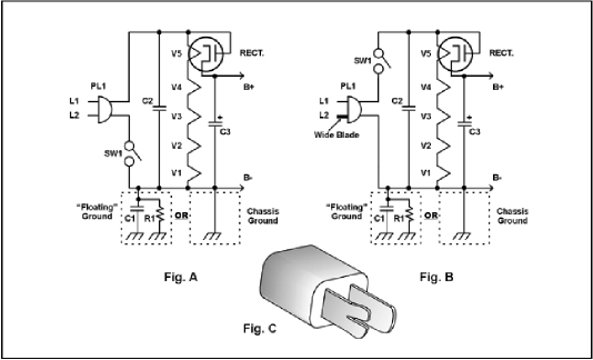
All of these radios had very similar circuitry, and alas, also had certain safety and reliability problems. The worst of these is the "hot chassis" problem. Since there is no power transformer, the circuitry is powered directly from the AC line. In many of these sets, one side of the AC line is connected directly to the chassis. (See Fig. A or B.) That means contact with the chassis could result in a nasty shock at best, and electrocution at worst.
Many sets relied on plastic knobs and cases as the only user isolation from the chassis, yet the screws holding the chassis were exposed underneath the cabinet, or the back of the chassis could be touched through openings in the rear cover. Many models employed a "floating" common bus, but since it was impractical to float the ground on the tuning condenser, it was necessary to have a fixed capacitor between the floating bus and the chassis for RF purposes. (See Fig. A or B.) While not a direct connection, typical values of .05-.25 Mfd used for this capacitor would still allow substantial AC current to pass, so the danger was not eliminated.
The final blow to any semblance of safety was the manufacturers' almost universal placement of the power switch in the negative or "ground" side of the circuit. This means that you are in danger no matter which way you happen to insert the plug. In one case, you are in danger when the radio is on, and in the other case you are in danger when it is off, since the "ground" is now connected to the hot side of the line through the resistance of the tube heaters. This is still more than enough energy to kill you. The manufacturers probably placed the switch in this location to keep it close to the potential of the volume control (on which the switch is usually located) to minimize hum.
With reference to Fig. A, assume that a human body is connected to an external ground. If the cord is plugged in so that L1 ends up the "hot" side of the line and L2 ends up the "neutral" side of the line, with SW1 in the closed position, the potential between the chassis ground and the external "real" ground will be close to zero, and you would be safe. But, when SW1 is in the open position, the chassis ground will be at the potential of the "hot" side of the line, because of the relatively low resistance of the tube filaments. There is more than enough current through this path to kill a person.
If we reverse the plug, putting the hot side of the line on L2, we have a similar result. With SW1 in the closed position, we have the full line voltage on the chassis. The only thing limiting the current flow through a human body would be the resistance of the body and the size of the fuse or breaker associated with the wall socket. With the switch in the open position, the hot side of the line is disconnected from the circuit, so we are safe as long as we leave the radio off.
The same condition exists with the "floating ground" circuit. The only difference is the amount of current that will flow through the R1 C1 combination. (R1 may not be present in all models, but is usually somewhere around 220K.) With C1 at .05Mfd, and assuming 60Hz, the available current is about 2.6ma. This may not be enough to kill you, but it is more than enough to cause heart fibrillation. With C1 at .22Mfd (not uncommon) the current available rises to about 9ma, enough to kill.
On the assumption that the restored radio is going to be played, and not just sit on a shelf somewhere, it is advisable to address these inherent problems along with the usual electrical restoration.
It is well known that the wax/paper capacitors are the most common components to fail. It is suggested that all of these be replaced with modern poly dielectric capacitors of at least 400V ratings. These are available from many sources.
The capacitor that is across the line should be replaced with a capacitor specifically designed for this use. (Shown as C2.) You can find these in the Digi-Key and Newark catalogs. Panasonic ECQ series capacitors are typical. They usually say 125VAC or 250VAC on them, rather than a DC voltage rating, and have the safety agency mark(s) imprinted on the capacitor body. This capacitor is critical because it is the one that must handle all the crap that exists on modern power lines. Light dimmers, electric shavers and the like may introduce spikes as high as 1500V on standard AC lines. The agency approved (UL, CSA, VDE) line bypass capacitors (called "X" capacitors) are designed to survive this kind of punishment. When the AA5's were made, such transients did not exist on the power lines. If you are making the polarized cord change, the capacitor shown as C1 in the figures does not have to meet this requirement.
The suggested safety modification is to use a polarized line cord, and rewire the AC switch in the radio so that the "hot" side of the line is switched. (See Fig. B.) If you are replacing the cord (which is often the case), you can replace it with a cord set that includes a polarized plug.
If you wish to keep the existing cord and plug, you can "polarize" the existing plug by cutting from the end of one prong into the hole in the prong with some heavy diagonal cutters. This will usually spread the prong enough so that it will fit in a standard socket only one way. If not, you can spread the prong apart a bit further. (See Fig. C.)
For new, polarized cords, use this procedure.
If you are keeping the original cord and plug, and doing your own "polarization" as described earlier, use this procedure.
What you are doing is rewiring the circuit so that the hot side of the line is being switched. (See Fig. B) The neutral side always stays connected, and thus keeps the chassis at a safe potential regardless of whether the radio is on or off.
The only hitch to this scheme is that the outlet into which the radio is plugged must be wired correctly. I suggest you purchase an inexpensive outlet tester at your local hardware store and go over all your outlets, making sure they are wired correctly. The suggested modifications to the radio will not interfere with the operation of any Ground Fault Interrupters, if they are present. (Schemes using a 3-wire cord will.)
To verify your work, set your meter to AC on a scale to read 120V. Check your outlet by measuring from the hole for the round ground pin or the screw holding the cover to, the slot for the wide blade. You should measure zero volts. (If you don't, the outlet is wired wrong, so do not proceed until that problem is corrected.) Leaving the ground lead in place, switch the other test lead to the slot for the narrow blade. You should read approximately 120V.
Now plug in your radio and measure from your ground to the chassis of the radio. You should still have zero volts. Try this with the radio both off and on. There should be no difference in the readings. (For an eye opener, try this measurement before you modify the radio, with the plug inserted both possible ways, and turning the switch on and off. Be sure YOU are not grounded during this test.)
With this modification, the switch and volume control are now at different potentials, so there is a possibility of hum being introduced. In all the sets I have modified, I have only had that problem once, which was solved by re-routing one wire. Careful lead dress during the restoration process should prevent any problems like this. (In other words, keep all leads as short as possible.)
If your radio has no back, there is a further hazard of contact with hot tubes or live connections. While most adults will have sense enough not to stick their hands into the back of an open radio, children may not. I've had good luck fabricating backs out of clear Lucite or PETG. Make a paper pattern, trace it onto the protective paper on the plastic, and cut the basic shape with a jigsaw. To insure adequate ventilation, drill a series of 1/4-inch holes about 3/4 inch from the top edge and the bottom edge. These are not critical, but the idea is to let air in at the bottom and out at the top.
You will also need a "mouse hole" for egress of the line cord, which you can make with a rattail file. If there were no "T" pins to hold the back, you can find a self-tapping screw that will thread snugly into the back mounting holes, but not so snugly that it might crack the case. Remove the protective plastic from your new back, de-burr the edges and holes if necessary, and screw in place. The nice thing about a clear back is that you can see the tubes light up when the radio is on.
Following these suggestions will result in a radio that will play for many years, and be as safe as any other modern household appliance. Bob Krueger, AB7CQ Web Administrator 146.920/146.320 PL 123.0 444.600 / 449.600 PL 100 Repeater IRLP Node: 7515 PL 114.8 ab7cqradio@ebidpal.com |